An Experimental Solid-State Kilowatt Linear Amplifier for 2 to 54 MHz
by Joel F. Paladino, N6AMG
This report is published as a tribute to Joel who passed away in December 1992.
Reprinted with permission from September 1992 QST; copyright ARRL
This article describes progress toward achieving a well-defined goal: building the smallest possible MF/HF/VHF amplifier capable of at least 1000 watts output. Nicknamed the Solid State Kilowatt (SSKW), the project has its roots in an article by Helge Granberg of Motorola in October 1986 RF Design. Two water-cooled amplifiers of that design, built by Mike Staal (K6MYC) of M2 had many problems. Some of them were device-related; others, power-supply related. (more about these issues later.) In February 1990 I rebuilt one of the water-cooled units using the old design and two new transistors. Optimized for 50 MHz, this amplifier could just reach the 1000-watt level. After using it for three weeks of South Pacific Dxpeditioning, I decided to construct an air-cooled unit. I spent the spring, summer and fall of 1990 building the SSKW and getting it ready for another DXpedition in the fall.
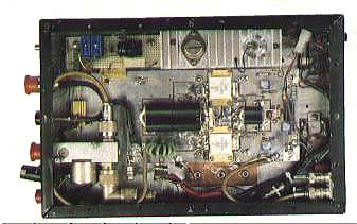
Motorola's article reprint AR-347 describes the basic amplifier design. July 1990 QEX also carried an article about it 2. Fig 1 shows the amplifier schematic. Briefly, the circuit consists of two MRF154 RF power MOSFETs in push-pull. Each of these transistors is capable of 600 watts output up to 100 MHz. The input and output transformers, 9:1 and 1:9, respectively, use cores of #67 ferrite material. The output transformer's 1:9 ratio is a compromise that is optimum at about 800 watts. Incorporating the Motorola building block into a DXpedition-ready package required experimentation and problem solving, as I described at the 1991 Central States VHF Conference 3. Here's where the system stands today.
The SSKW includes TR relays that bypass the Fig 1 circuitry in receive mode. I designed their control circuitry to eliminate the possibility of the high RF fields in the amplifier compartment causing relay falsing problems, and to simplify field repair by keeping parts count low. The relays are sequenced to allow the output relav to close before the amplifier puts out power. Because relays take a few milliseconds to operate, sequencing is necessary to keep the relay from hot-switching the amplifier output. (Hot-switching 1 kW will destroy a relay rapidly!)
This design has two small problems. For the short time it takes the amplifier's input relav to close on switching from receive to transmit, the exciter operates without a load. This can be remedied by delaying the exciter keying. The other problem is the relay's closure time changes as the relay heats. This can be solved two ways: Use external electronics to do the delay, or temperature-compensate for the resistance change.
I haven't yet built SWR protection into the amplifier. In January 1983 QST, Helge Granberg described an SWR protection circuit for a 2- to 30-MHz amplifier 4. A phone conversation with Helge indicated that this circuit will work to 54 MHz, so it should suffice. How much mismatch the MRF154s can tolerate is unknown, however, so I don't want to use the SSKW to calibrate its own SWR-protection circuitry!
The amplifier's output can be reduced two ways: by turning down the exciter power via amplifier-generated ALC, or by reducing the amplifier bias. (These are enhancement-mode FETS so positive bias is necessary to turn them on.) The ALC option is better because it does not affect the amplifier's linearity. A no-output-load condition must shut down the amplifier as quickly as possible.
Overdrive can destroy power MOSFETs instantly, so a drive limit control is essential. A threshold detector should be incorporated. The SSKW's input includes a 5 dB attenuator so 100-watt exciters can drive the amplifier without damaging it. If the 5 dB pad fails to attenuate, or if the exciter puts out too much power, the amplifier must be shut down rapidly.
The amplifier must also be shut down if the transistors flange temperature exceeds 40 oC. Shutdown can be done two ways, depending on how the amplifier is used. The first way is to just turn down the bias, which changes the amplifier's linearity. The second way is to totally turn off the amplifier. This must be done gracefully so the amplifier does not shut down while producing full power. The following shutdown sequence is essential: (1) turn down the bias; (2) open the input relay; and (3) open the output relay.
The SSKW's bias circuitry is straightforward. R8's value must be tailored to the particular MRF154s used. If the bias decreases too fast with rising temperature, increase the value of R8. The LM723's input voltage must never exceed 40 volts.
Filtering must be added to make the amplifier comply with FCC signal-purity regulations. The reactance of these filters away from their intended passbands must be taken into account. Absorptive low-pass filters should be considered. Such filters dissipate harmonic energy as heat rather than reflecting it back to the amplifier transistors.
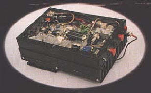
I intended to make this amplifier as small and light as possible. Most of the amplifier's weight is its aluminum heat sink and copper heat spreader. How much heat sinking is needed depends on the duty cycle required. I decided that a duty cycle of 50%or less was acceptable. The resulting weight for the package, 14 pounds, is very acceptable. The SSKW is 8 inches wide, 12 inches long and 5 inches high.
The key to making the package light was to use the smallest possible heat spreader. I decided to use enough � inch-thick copper to surround each MRF154 with at least 1 inch of spreader. I machined the spreader flat and attached it to the heat sink, also machined flat. After attaching the copper to the aluminum, I resurfaced the copper again at the transistor contact points to insure flatness. I spread a thin layer of beat-sink compound between the copper and aluminum, and another layer between the copper and the transistors.
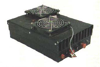
With two high-pressure, 24-volt fans blowing on the sink, the resultant duty cycle limit is a little less than 50%. These fans are in series across the amplifier's 50-volt supply. The small fan in the compartment is a 12-volt unit that just barely fits. (The compartment needs to be a little deeper.) A fan is necessary here, However, because compartment airflow dramatically keeps the output transformer's ferrite from getting hot.
A heat sink with more fins and a thicker base, but the same fin depth, would raise the duty-cycle limit. (The copper spreader should be made larger as well.)
These changes would also make the amplifier heavier.
A milling machine is required for surfacing all of the amplifier's heat-conductive interfaces. Physical flatness is essential for maximum heat conductivity and to avoid warping the transistor cases. The Motorola bulletin specifies the torque of the screws on the MRF154�s flanges. Tightening these screws uniformly assures that the flanges won't warp during temperature cycling. R14 and R15, the feedback resistors, are flange-mounted. Their beryllium copper leads cannot be flexed very many times before they break. (According to their manufacturer, that may be only once!) These two resistors just barely fit. So, make sure the wo MRF154s are separated properly.
To keep the amplifier small and light, I use a switching power supply . A Lambda LFS 50-48 (net weight, 20 Pounds) does the job, with good results, sized at 15 inches long, 7.5 inches wide and 5 inches high, it can source 50 amperes at 50 volts. This power supply produces significant radio noise up to 30 MHz, most of it radiating from the supply's ac-line leads. I EMI-filtered the supplies leads with good success. Because linear supplies generate little or no RF EMI, they are superior to switching supplies for fixed station use.
Overshoot is a regulated power supply characteristic that's particularly troublesome in switching supplies. Overshoot occurs when a regulator responds too slowly to keep its output voltage down in response to short-duration, high-current loading. In a 50-volt switching supply, and depending on the load, overshoot transients of more than 100 volts may result. I've seen overshoot destroy expensive transistors! The SSKW supply must be able to safely handle the variable power-supply demand that occurs during SSB and CW transmission. Power-supply RF sensitivity is another consideration. Some power supplies are sensitive to RF. Their output voltages may vary with the presence and amplitude of RF on their input and output leads. The SSKW's supply must be free of such effects.
Be careful when applying dc to the amplifier for the first time. Do not use a high-current supply for initial tests. Use a current-limited, 3- or 4-ampere supply to check the regulator and set the bias. The amplifier should have a reverse polarity protection diode rated at a voltage appropriate to the supply. Make sure that you have a 50-ohm load on the amplifier output, The bias circuitry may not act correctly if there is no load. Slowly increase drive. Watch the output power and the current drain to make sure they are in line with efficiency. If the input match is bad, check C7 and C8. If the amplifier does not achieve its efficiency capability, RF that doesn't make it to the load may try to leave via the dc input line. This can cause C12 to explode off of the underside of the board. Also, under normal operation, the single unit Motorola specifies for C12 can barely handle the RF current that passes through it. I recommend paralleling 100-volt, 0.05- or 0.1mF chip capacitors instead of using a single 0.1mF chips. This problem is difficult to analyze because C12 is on the underside of the board.
As mentioned earlier, the SSKW�s bias circuitry may have to be tailored to the particular MRF154s used. One thing not mentioned on the schematics is the addition of an Arco 365 variable capacitor (C15 in Fig 1) across C14 to cancel some of the inductive reactance in the output transformer at 6 meters.
With a 50-volt power supply, the SSKW can produce over 1.1 kW from 2 to 54 MHz. At this power level, the MOSFETs� drain current runs at around 40 amperes, depending on the operating frequency. The SSKW can produce up to 1.5 kW below 30 MHz. Especially below 30 MHz, the SSKW's harmonic output rises with output power. It may be possible to use only four low-pass filters to cover the 2 to 54 MHz range if a second harmonic of - 40 dB can be tolerated. Since the transistors operate in push-pull, the second harmonic is usually not a problem. Without its 5-dB input pad and operating with a 50-volt supply, the amplifier exhibits an input SWR of less than 2:1 (referred to 50 ohms) throughout its frequency range. Only below 5 MHz does its input SWR exceed 1.6: 1. Inserting the 5-dB pad adds 10 dB of return loss and keeps the input SWR below 1.3:1 through the amplifier�s operating range. I have not yet measured the amplifier's two-tone, third-order IMD performance.
For now, I can say that my goal of a compact, lightweight amplifier capable of at least 1 kW output is a reality. The SSKW has served me well in its intended DXpeditionary application. Nonetheless, the amplifier in its present form is still experimental. Before the SSKW could be acceptable for general use, output filtering and failure proof protection circuitry would have to be added, The next generation is on its way. The next project? Use the same 50-volt supply with power FETs capable of covering 144 to 432 MHz, and build it into a similar package!
I thank Helge Granberg for spending considerable time answering questions about this project,
Notes:
(1) H. Granberg, "New MOSFETs Simplify High Power RF Amplifier Design, RF Design, Oct 1986, pp 43-48,50,52.
(2) Paladino, �A Rapid Deployment Prototype Solid State Kilowatt Linear Amplifier for 2 to 50 MHz Using MRF154s, �1991 Central States VHF Conference Proceedings (Newington: ARRL, 1991), pp 61-70. Available from the ARRL Bookshelf as #3614.
(3) H. Granberg, "MOSFET RF Power - An Update, " Part 2, QST, Jan 1983, pp. 30-33; also see Feedback. QST, Mar 1983, p 44. (Part 1 appeared in QST, Dec 1982, pp. 13-16; also see Feedback., QST, Jan 1983, p 48.)
(4) American Technical Ceramics (ATC) has some new chip caps (the 900 series) that have higher voltage and current ratings than the capacitor Motorola specifies. I have samples but have not tried them yet.
Joel Paladino became a radio amateur in 1977 and holds an Extra Class license. His present interests are split between small-signal DXing from 50 MHz (his favorite) to 24 GHz, and 440- and 902-MHz repeater networks. Joel has also operated EME on 50, 144, 220 and 432 MHz. He Presently has a 10-meter-wide computer-controlled dish for 432-MHz EME and two 50-foot 6-meter Yagis at 100 feet for F2 DXing and EME. During the most recent solar-cycle peak, he DXpeditioned to rare 6-meter countries and operated CN2JP (the SSKW amplifier has been to Morocco twice), CU3/N6AMG, KH8/N6AMG, 5W1JP and VK9LG. Joel assisted with ARRL's Radio Frequency Interference: �How to Find It and Fix It� and intends to write on repeater topics. After over ten years of engineering and installation work for Motorola and Chevron, Joel has worked full time in his own land mobile and micro wave consulting business since 1990. He is unmarried and has no children. His other hobby is mountain-bike riding.