GJ4ICD's Compact 8877 50MHz Amplifier
 Main Features include: Main Features include:
Mini Compact Units
Large Easy to read Meters
1.8 KvaToroidal Transformer
Slow Start Safety Circuit
Filament In-rush Protection
Strong Die-cast Chassis
Just 2 15kv 1.2Amp Rectifiers
Protection Timer
Switch/Circuit Breaker
Simple to Reproduce
Simple to Build
-60db Harmonics + 1/4 wave Stub
Full Internet Parts Listing
WARNING: THIS PROJECT CONTAINS VERY HIGH VOLTAGES.
The reason for building this amplifier is to conduct Ionoscatter/Troposcatter along with FAI tests, it has been good fun, and, a good building exercise
in producing an amplifier so compact and clean, and which has been duplicated from these pages 5 times so far (7/3/98).
It was decided to use an 8877 triode tube as the 3rd order IP's are -41db compared to a pair of 3CX800's which are -36db. This offers the best possible spectral signal.
UK amateurs are only allowed 26dbw (400w) of which tests so far indicate only weak Troposcatter/Ionoscatter signals enhanced by Meteor bursts/burns at the 1200 kms mark. A special permit has
been issued for this amplifier which permits 30dbw at the antenna feedpoint.
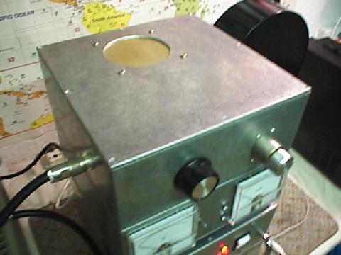
PSU AND RF DECK VIEWS.
A chassis was needed and after careful consideration it was decided to use the 3CX800A7 diecast metalwork box idea design on our other Internet pages.
Die-cast boxes are very strong, albeit a pain to drill and work with, 2 Radiospares boxes were ordered from here , (the xyl paid for these as a birthday
present!) these were 10" square and 4" high, they were mounted back to back (or bottom to bottom) after cutting all but 1/2" out of one of the boxes (similar to the 3CX800 design).
Above is both the PSU and the RF deck, note the RF relays on the side of the RF deck, these could be fitted on to the rear of the RF deck if preffered and then the 2 units could be bolted
together side by side, or, the units can be stacked on top of each other if required. The meters are about 3 1/2" square and are available from RS Components, no shunts are needed. All the
metalwork was done with standard hand tools and an electric drill, no special hole cutters were used due to the size of the holes needed.
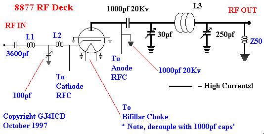
Here is the 8877 circuit.
AMPLIFIER PARTS LISTING
ANODE SECTION:
RS Die-cast Boxes # 225-271 (2 needed for RF deck)
N Socket RS # 223-9575 (Don't use SO/PL259 types!)
RFC2 (Anode Choke) 50t of 22swg on 3/4" PTFE Rod. ( winding is 1 3/4" long, rod length is 3 1/4" with tapped hole in one end for support). You will have to make
this choke.
The Z50 output choke is made from 1/4" teflon/tufnol rod, 1 3/4" long, the winding is 1 7/16" long and is approx 66 turns of 28swg, this is connected across the
output socket.
A Miller RFC50 can also be used here which is 68 turns of 32 swg on a 1/4" tufnol rod, however, an even better approach is a 1/4 wave shorted stub on the output connector, this has two
functions, a) it will trip the PSU if the blocking capacitor goes short, and b) it attenuates 100MHz by over 30db. The stub length is around 40" but start with more before trimming, and use good
quality coax.
Anode tuning capacitor is a 30pf 15kv variable vacuum type CADD 30 15 found Here
Anode tuning coil is 3 turns 1 1/4" in diameter and about 3" long made of 1/4" tubing.
Loading capacitor is 259pf widespaced CAV 75 37 found Here
Eimac 8877 Tube plus Eimac matching socket and chimney available Here or from RF parts in the USA
Here (Socket # SK2210, Chimney # SK2216).
1000pf 20kv Erie Doorknob capacitors for the blocking and decoupling of the EHT.
EHT Connector plug /skt from Surplus Sales Nebraska. (15kv Kit) Here!
The EHT kit has both plug and socket plus lead and is coded Alden (CNE) 8101SET $14.
(note only one is needed).
CATHODE SECTION:
8877 Filament Transformer 5v 10 amp, 12v 1 amp from Surplus Sales Nebraska Here!
or from Peter Dahl Here (Make sure that you order 110v or 220v AC).
12 Volt 50 or 75 watt Zener for Bias. ( Farnell Components Ltd ) # BZY91C12
A small pcb fuse holder and tag board for the bias circuit, single pole 12volt relay for the bias circuit available Here
Tag Boards for above are available from RS, part # 433-725 (pack of 5)
A 2 amp bridge for the 13.5 volt supply with suitable electrolytic capacitor found Here
A 10k 12 watt wirewound resistor that is shorted out on TX. Farnell Components Ltd
A 220 ohm 12 watt wirewound resistor that shunts the cathode fuse and Zener.
You can use 2 and 4 pin Mic plug/sockets for the LT/B- and earth lines.
CATHODE RF SECTION: (This is a duplication of the 3CX800 input circuit)
Input capacitor 3600pf silver mica 500v. (RS # 495-919)
L1 is 10 turns of 18 swg 5/8" in dia tinned copper wire:
L2 is 10 turns of 18 swg 5/8" in dia tinned copper wire: (both coils are the same).
C1 is 100pf Jackson type capacitor C804: # FF48C (Maplin Here ) or similar.
Cathode RFC (choke) 48 turns of 22swg enamelled on 1/4" tufnol former.
Heater choke (RFC). 15 turns of 16swg enamelled on 1/2" ferrite rod. Note that this is a bifilar winding, in other words two lengths of enamelled covered wire wound side by side on the 1/2"
ferrite rod covered with heatshrink first.
Meters are available from RS # 258-912 for the 1 amp anode meter and # 258-906 for the 100 M/A Grid meter. They can also be obtained from UK company CPC Ltd, Tel 01772 654455. 1 amp
Meter is PM11122, 100 M/A Meter is PM11199, Back lights PM11191 2 packs.
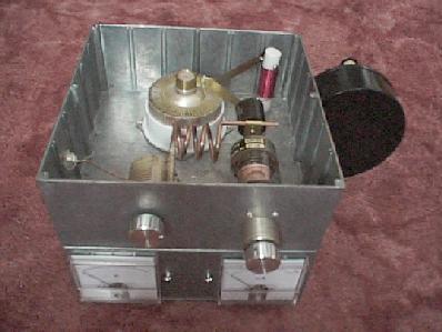
The Bits!
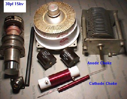
Above can be seen the 8877 plus loading capacitor, also the "space wound" cathode choke along with the main anode RF choke wound on PTFE stock.
The capacitor on the left is a 30pf Variable Vac' type at 15kv, the two capacitors in front of the tube are 1000pf 20kv doorknobs, one is used as the "blocking" capacitor from the tube to the
tuned circuit, the other is used as a decoupling capacitor for the high voltage.
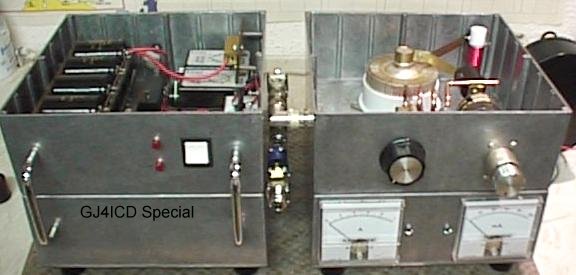
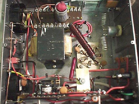
RF DECK.
Here is the RF deck, it consists of 2 10" square RS die-cast boxes # 225 271 bolted back to back. they are 4" high. The bottom box contains the metering
circuit, bias relay, heater transformer, bifilar filament choke, and RF input circuit. The large meters are well screened from RF and also well decoupled with 1000pf disc ceramics. The lefthand
meter is 1 amp for anode current, and the right-hand meter is 100 m/a for grid/cathode current.
The top box contains the 8877, Anode choke, and Pi-L tank circuit. Note the strap between the RF choke, the anode head and the 1000pf 20kv isolating capacitor, this is made from 1/2"
wide brass stock, it also forms the anode connection. The tuning capacitor MUST be a variable vacuum type and is mounted on the front of the box.
The anode tuning coil is 3 turns of 1/4" copper tubing and is 1 1/4" in diameter as shown above. A high power blower is fitted to the right-hand side. (see notes below)
The total height of the RF deck is just under 8". On the back bottom box is the mains input IEC connector (this is fed from the psu), 2 pin mike skt for the 13.5 volt input, 4 pin mike skt
for the B- and Earth returns and 3 phono/RCA sockets for power to the coaxial relays and PTT line, 2 fuse holders, one for the mains input to protect the filament transformer and blower,
the other one protects the 13.5 relay supply. A PTT switch was fitted at the side of the LED's, this is not visible in the above photo. There is also the tuning input capacitor and RF input
socket. The lid vent is meshed with fine strong mesh.
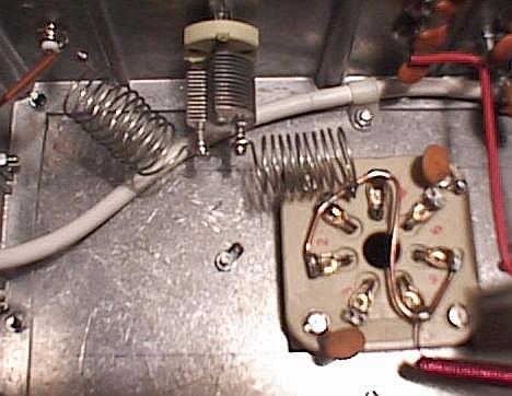
RF DECK UNDERSIDE.
Above you can see the filament transformer near the centre, to the right is the 8877 base.
Top right is the RF input circuit which is a copy of my 3CX800A7 input circuit.
3600pf input from the BNC socket, then coupled to the first coil which goes to the 100pf tuning capacitor, the second coil fits between the 100pf cap' and the tubes cathode. All cathode pins
on the socket are shorted together. Pins 1 & 5 are for the big bifilar choke.
Bias board/Zener and cathode choke are at the bottom on a tag board. The big capacitor at the top of the picture is the motor start capacitor. The meters are to the left of the picture
and are decoupled with 1000pf 4 kv cap's.
Power Supply
PSU Parts Listing.
RS Boxes # 225-271 (2 needed for PSU)
Laminated board to mount Electrolytics RS # 433-523 (1 needed)
Switch/Circuit Breaker RS # 212-2001 (15 amp) RS Components
3 Minute Timer RS # 349-888 (Must be used) (240vac) Here
20 Second Timer for in-rush circuit set at 3/4 seconds from RS # 349-872 (240vac)
2 15 ohm 100 watt metal clad power resistors for in-rush circuit. RS # 188-138
20 amp Mains Relay for in-rush circuit from RS # 245-2431 (240vac) Here
8 Electrolytics 220mf 450vdc RS # 2280-630 stud mount, or, RS # 116-701 (1.45 amp ripple) 220mf 400vdc clamp mounting. Here or anything similar
will do.
Equalising resistors for electrolytics RS # 199-6148 (47k 12w 8 of) from RS Components
50 ohm 50 watt metal clad resistor (series EHT feed) RS # 160-988
ILP Toroidal HT/Relay Transformer 1.8 kva. AMP UK 12.5 kilos. Cost 175 UKP
2 15kv PIV 1.2 amp stick rectifiers ( Peter Dahl ). I also have lots of these which are good for 3CX800 amplifiers as well, try
Here
The power supply is also made in two boxes same as the RF deck, the main transformer, a toroidal, measures 8 1/4" in diameter and 3 1/4" in height and
weighs a mere 25 pounds fits into the bottom box, the leads are brought into the top box via rubber grommets to stop any chaffing to the leads, a sheet of 11 thou PTFE 9" in diameter was cut to
double insulate the transformer, WARNING! Countersink ALL the holes in the bottom box, ie: the ones used to mount the diodes and any other components,
otherwise the screw heads may damage the transformer! all the other circuitry fits into the top box, this makes the 2.6kv (on load) power supply extremely compact and
serviceable.
TOP VIEW.
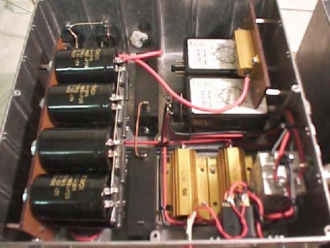
The power supply: As can be seen in the picture the EHT capacitor stack is mounted on a board on the left-hand side, these electrolytics have bolt
mountings, DO NOT mount them on to any metal surface as the bolt is also the negative connection! I mounted them on a small piece of insulation board and then used
6ba standoffs to isolate the board from the chassis, the 2 main 15kv diodes are to the right of the EHT capacitors, DON'T use strings of diodes in place of these units as they are a poor
substitute unless shunt capacitors and transient resisitors are also fitted across each diode, plus, if one or two diodes go short in any of the legs you should really change the whole lot!, the
2 in-rush 15 ohm 100 watt resistors are further to the right and the relay (20 amp rated) is placed on the right-hand internal wall, the in-rush circuit is controlled by a short 4 second RS
timer.
The 2 timers are installed at the rear right. (one not shown connected when the picture was taken).
The B-, Earth and 13.5 vac are taken out of the PSU to the RF deck, 2 and 4 pin screw type microphone connectors are used to secure the connections on the RF deck.
The bottom box houses the main toroidal transformer which provides the EHT and 13.5 volts for the bias/RF relays on the RF deck. The 13.5 volt supply is controlled by the 180 second timer to
ensure it is NOT possible for the RF deck to go into TX until it's cycle is completed. The DC components for the 13.5 volt supply are placed in the bottom of the RF
deck along with the heater transformer and bias components, they all are fitted on a tag board and isolated from the chassis using standoff pillars.
UNDERSIDE VIEW.
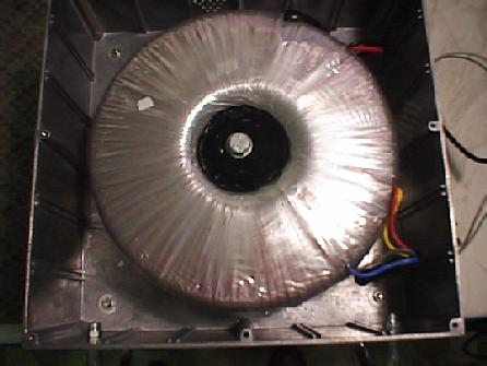
The massive toroidal transformer in the bottom box mounted on a sheet of PTFE, also note that the leads are fed through the chassis with rubber
grommets. Countersink all holes that are drilled in the bottom box to stop damage to the transformer!
This transformer is 8 1/2" in diameter and 3 1/2" high, it weighs 12.5 kilos! and is mounted by one center bolt.
POWER SUPPLY CIRCUIT.
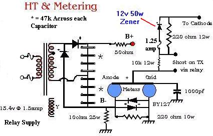
The above voltage doubler circuit is really the same as for a 3CX800 amplifier, the only difference is that the transformer is "beefed" up and the Zener
diode is a 12 volt 50 or 75 watt version (isolated from chassis). Use 15kv 1.2 amp diodes (2 of) and not strings of el cheapo diodes in the doubler circuit, it makes sense, as, unless you
include shunt capacitors (to eliminate any white noise) and transient resistors across each diode they WILL eventually blow, this will usually happen when dx is on the band!
Also please note that 2 timers are used in the primary circuit, one controls the in-rush circuit and the other, a 3 minute timer, controls the 13 volt relay supply.
SLOW START CIRCUIT
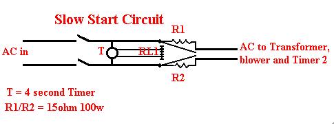
The above slow/soft start circuit is controlled by an RS timer module, after 4 seconds the power resistors are shorted out by RL1 which is a 20 amp
mains operated relay, power is then taken to T2 a 180 second timer and blower/filament/eht etc.
A word of warning here! Eimac recommend 3 minute pre-heating on 8877's and 3CX800's, YOU MUST use a 3 minute timer to prevent damage
to these expensive tubes!
* indicates that there is a balancing/bleeder resistor across each electrolytic capacitor the value being 47K at 12 watt.
The anode meter is 1 amp rated, the grid meter is 100 m/a rated, there are 2 1N4007 or BY127 diodes across the meters to protect them.
The EHT positive line has a 50 ohm 50 watt metal clad resistor in line in case of any arcs, this method is preferred to a fuse, don't use fuses in the eht supply as all they will do if there
is a problem is explode! Make sure that this resistor is isolated from the chassis. (this can be seen in the top view of the power supply, top right-hand corner).
OPERATING/SETTING UP DATA.
Before applying any power to the RF unit grid dip the input and output circuits with a GDO or Spectrum Analyser/sweep generator for return loss with the
tube inserted, make sure that you connect a 50 ohm dummy load to the input and output connectors if you use a GDO when you do this. This should at least give you an idea if the circuits are
resonant.
Double and triple check the bias/relay wiring, remove the tube and apply the filament volts, they should be 5v AC +/- 5% to preserve tube life, only use a digital meter for this measurement
as analogue meters are not accurate enough, if all is ok then switch off and insert the tube.
Before running the amplifier I suggest you leave the blower and filaments on for 10 hours to burn in the tube for longer life.
The toroidal transformer I used has 2 500v AC secondary windings, to set up the amplifier I first of all used only one of the windings into the voltage doubler, this produced around 1.4kv off
load which is ideal for testing purposes. (the other winding would be added in series later!)
Switch on the power supply, the blower will start along with the filament voltage present, after 4 seconds the slow start circuit will switch in and bypass the 2 100 watt metal clad resistors
(a clunk as the relay changes over), you now have to wait for the 180 second timer to complete it's cycle, when the cycle is complete short the ptt line to chassis, this should show standing
current on the Anode Meter of around 50 m/a due to the low HT.
OPERATING CONDITIONS
ANODE VOLTS. ANODE CURRENT. GRID CURRENT. DRIVE. POWER OUT.
1400Vdc 50 M/A
0 0
0
1300Vdc 600 M/A (50 M/A) 40 M/A
20 W 400 W * 13DB
2800Vdc 80 M/A
0 0
0
2600Vdc 700 M/A (80 M/A) 20 M/A
32 W 1000 W *
2600Vdc 800 M/A (80 M/A) 20 M/A
40 W 1200 W * 14.5DB
2600Vdc 900 M/A (80 M/A) 25 M/A
50 W 1500 W * 14.5DB
Note: Grid current is reduced at higher plate potential:
* Measured on Bird 43 on input and output into Bird 1 kw load. Input VSWR was very low 1.2/1. All capacitors in the input and output cicuits were half meshed, no adjustments were
needed to any of the input/out coils. (the first time ever I have built an amplifier that never needed any adjustments!)
The KW
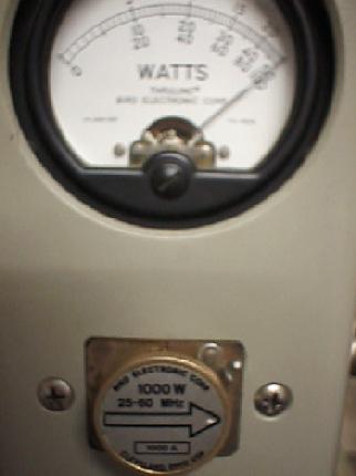
Sorry the picture is out of focus, but it was a little hard to key the FT920 and take the shot at the same time! This shot was taken at around the 700
M/A level (1kw out).
ADDITIONAL NOTES
If you intend to run this amplifier above the 1.5Kw level I would suggest the following.
Replace the loading capacitor with a 300pf variable vacuum type.
Use a vacuum antenna changeover relay, or sequential switch lower power relays.
Fit a grid over-current trip circuit.
Cooling Notes.
I used a capacitor start single phase 2800/3300 rpm blower, it is 7 1/2" in diameter and is rated about 200 cfm, it is noisey and is far beyond the
requirements of the 8877. The blower is 240 volt AC but on receive can be run at 110v AC by tapping off the filament transformer via a small relay if you wish, this eliminates much of the noise
on receive.
Blowers are available Here at Surplus Sales in Nebraska.
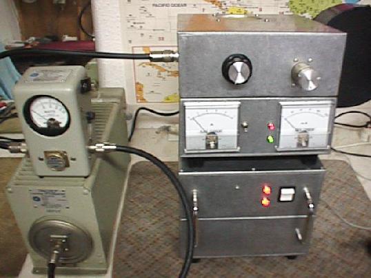
Another completed view of the RF deck and Power supply shown in the "TX" position.
Output Ventilation
Here is the top view showing the lid meshed with high quality Brass mesh, the mesh is supported by a square of double sided PCB that is bolted to the
lid and then the hole is cut out of it. Halfords in the UK stock a DIY Aluminium mesh for car repairs, this is ideal for the above.
Input Circuit
Here is a close up of the cathode tuned circuit, the BNC on the left back wall feeds the input matching 3600pf capacitor, this in turn is connected to
the 100pf tuning capacitor via L1, L2 is fitted between the tuning capacitor and the Tube base cathode connection. Note the 2 decoupling capacitors on pins 1 and 5, these are for the
filaments.
Anode RFC and EHT Connector
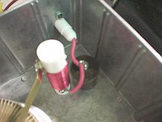
Here is the anode RF choke with 1000pf 20kv doorknob. The psu also has the same decoupling capacitor installed in it. The
EHT connector was from Surplus Sales in Nebraska.
Tube and Anode Tuned circuit
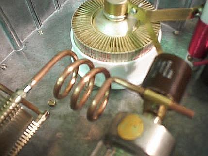
Close up of the Tube, Anode variable vacuum capacitor, 1000pf 20 kv isolating capacitor, anode tuned circuit, and loading capacitor. The anode coil is
tapped 4 ba to screw onto the loading capacitor bolt, it is then Silver soldered.
Another Top View
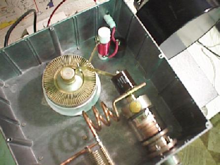
Another view of the plate compartment showing all the circuitry involved and how very simple it is to build. Not viewable on the left is the "N" type
output socket, this has the Z50 choke across it to chassis to prevent the HT reaching the antenna if the main blocking capacitor goes short circuit.
(Print these pages out for a better view!)
ANALYSER SHOTS.
It is difficult to get good shots with a digital camera due to lighting conditions, Centre frequency is 100MHz, Horizontal 20MHz per division, Vertical
10db, this is a sweep of the amplifier which is clean at -60 db+. Power output is 1kw
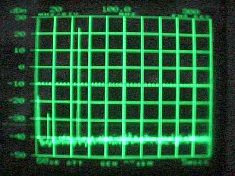
The amplifier and power supply have been given an independent check over by Broadcast Engineer Dennis GJ3YHU. The output
was found to be -60db at 150MHz and around - 57/58db at 100MHz.
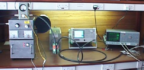
Here's the professional test facility kindly provided by Dennis GJ3YHU, the unit was tested both "cold" and "hot". The tests proved we had a nice clean
amplifier.
PARTS SUPPLIERS.
Toroidal Transformer. From Amp UK. Here Beware! it is heavy (13 kilos) and will be VERY costly to
transport outside of the UK. It is purpose designed for 2 3CX800's and also has the 13 volt 3CX800 filament supply.
Variable Vacuum Capacitors from Surplus Sales Try Here! you can also get the diodes, isolating capacitors (1000pf 20kv) the
bifilar choke, the electrolytic capacitors, filament transformer, the tube, base and chimney, in fact most of the bits can be obtained from Bob Grinnell, you can email Bob
Here
Send for his brilliant full photo catalogue Here
The main boxes are from RS Components in the UK. They also have branches around the World, this is their WWW site, the part # is in the listing.
Please remember, if you are going to buy all new bits then it will be an expensive project, but still cheaper than buying a new Henry Tempo 3006 at £3,000 plus in the UK!
DISCLAIMER
NO LIABILTY CAN BE PLACED UPON THE WRITER OF THIS ARTICLE
FOR DEATH OR INJURY SUSTAINED IN BUILDING THIS PROJECT
THANKS/ACKNOWLEDGEMENTS
Radio Handbook, Bill Orr, W6SAI (slow start circuits for power amplifiers)
Ham Radio July 1986. (A 6 Meter Kilowatt asmplifier by KX0O)
CQ June 1987. (An Easy to build 8877 for 6 Meters by Steve Katz WB2WIK)
ARRL Handbook. ( A 3CX800A7 Amplifier for 6 Meters)
Eimac USA. (8877/3CX1500 Operating notes)
Ham Radio Today. (Nov/Dec 1996/Jan 97. A 3CX800A7 Table top amplifier GJ4ICD)
Dennis Robinson GJ3YHU (for independent sweep of amplifier)
Designed and Built October 1997 Copyright GJ4ICD
|