
Final comments
I have to say I'm really pleased with the way this project has gone. It has been a little ambitious in that I had two transformers and a case made especially for the design. However, I could not have met my objectives if I hadn't had done so I suspect!
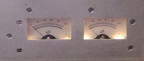
The meter board fits and they light up, phew!
The two meters (grid current [200mA] on the left and anode current [1A] on the right) are lit by four bulbs driven from the delayed +12v output of the control card.
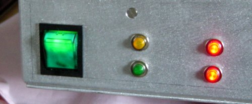
Three minutes always seems a long time!
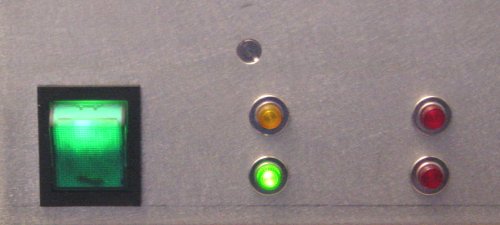
Green means I'm ready to go!
I did not encounter any major problems or serious design errors and would be happy to recommend any one who wants to replicate the design to go ahead and do so. BUT PLEASE REMEMBER THAT LETHAL VOLTAGES ARE USED AND ONE MISTAKE COULD PROVE FATAL SO DO NOT ATTEMPT TO BUILD THIS DESIGN IF YOU DO NOT HAVE THE APPROPRIATE EXPERIENCE!
Now, all I need to do is to go on a 6m DXpedition...
Chris, G3WOS (ZD8SIX, VP8DBL)
Farnborough, UK
May 2002
g3wos(at)uksmg.org